3D Printing Tolerances: What to Actually Expect
A CAD model is dimensionally perfect. A printed part never is. The gap between the two is tolerance, and it’s the single most common reason a first-run 3D printed part doesn’t fit the way it did on screen. The gap also isn’t fixed. It moves depending on which process printed the part, and by how much depends on which one you picked.
Why Tolerance Varies This Much by Process
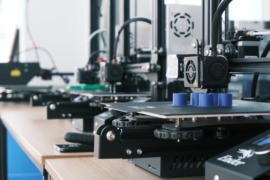
Tolerance in 3D printing comes from how the process actually builds material, not from a single accuracy spec you can look up once. FDM tolerance is limited by nozzle diameter and layer adhesion between extruded lines. SLA tolerance comes from laser or projector resolution curing a liquid resin in very thin layers, which is why it holds tighter features than an extrusion-based process ever will. SLS and MJF sinter powder without support structures, which removes support-related distortion but introduces its own shrinkage and thermal behavior. None of these processes are more accurate in some universal sense. They’re accurate differently, for different reasons, and design decisions need to account for which one is actually running the job.
What Each Process Actually Holds
Independent process testing, including Formlabs’ published accuracy and tolerance guidance, puts general-purpose FDM in the ±0.2 to 0.5 mm range depending on part size and printer quality. SLA holds meaningfully tighter, commonly ±0.05 to 0.15 mm on small to mid-size features, with tolerance widening slightly as feature size increases. SLS and MJF typically land around ±0.3 mm or a percentage of part dimension, whichever is larger, with the advantage of no support-induced warping since the powder bed itself supports the part during the build. DMLS for metal holds tighter dimensional control than the polymer processes but usually needs a post-machining pass on critical features to hit final tolerance, since the process is built for geometry and material properties first and finish-machined precision second.
Tolerance Isn’t the Same Question as Minimum Feature Size
Designers sometimes conflate the smallest wall a process can print with how accurately it holds a dimension, and they’re two separate limits. A process can successfully print a thin wall and still miss the target dimension on that wall by a meaningful margin. Both numbers matter for a working design, and they don’t move together. Checking one without the other is how a feature prints successfully and still doesn’t function.
Design for Fit, Not for the CAD Number
Mating parts need clearance built in, not just accurate dimensions on each half independently. A shaft and bore that are each individually within tolerance can still bind or rattle if the clearance between them wasn’t designed with the process’s tolerance range in mind. As a starting point: snap fits and sliding fits in FDM generally need more built-in clearance than the same features in SLA or SLS, simply because FDM’s tolerance band is wider to begin with. Press fits are workable in the tighter-tolerance processes but are a poor match for FDM, where dimensional variation makes a reliable interference fit hard to hit consistently. None of these are universal numbers. They’re starting points to verify against the specific process, material, and printer actually running the job.
How the Industry Actually Tests This
Tolerance claims aren’t just marketing copy. The additive manufacturing industry has a standardized way to measure it: ISO/ASTM 52902 defines a set of benchmark test geometries used to assess the geometric capability of an AM system under controlled conditions. When a process or a shop’s tolerance numbers trace back to this kind of standardized testing rather than a best-case example, that’s a meaningfully more reliable number to design around.
When Printed Tolerance Isn’t Tight Enough
Some features simply need tighter control than any additive process delivers as-printed. That’s a real design decision point, not a reason to force a printed part into a role it can’t hold. A secondary machining operation on critical features, a design that moves the tight-tolerance feature to a mating part in a different process, or a transition to CNC machining or molding entirely are all legitimate answers, and which one is right depends on the part, not a rule of thumb.
Send us the drawings and our team will walk through which process actually holds the tolerance your design needs, and where a print alone won’t get you there.