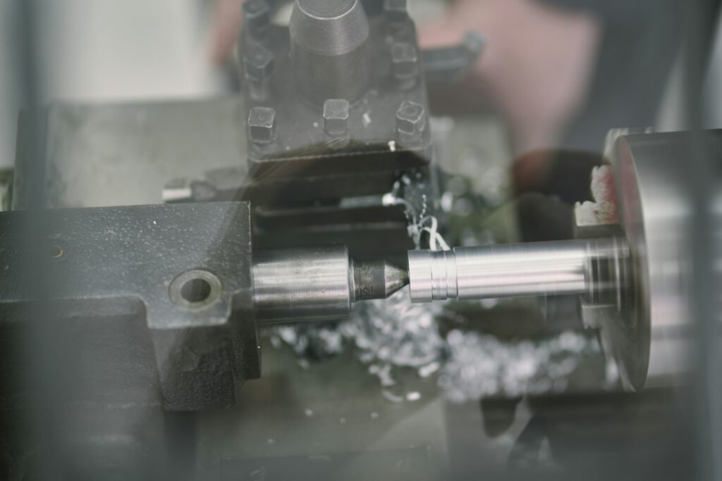
Shafts, pins, bushings, spacers, fittings, and fasteners make up a large share of the parts in any assembly, and nearly all of them are CNC turned parts. Turning is fast and accurate for round geometry, but a few design choices decide whether a part runs in one quick setup or needs slow cuts, extra operations, and a second machine. These rules apply to conventional CNC lathes, mill-turn centers, and Swiss-type machines.
Design for the bar stock
Turned parts start as round bar. Size the largest diameter just under a standard bar size so the shop isn’t turning away a lot of material. If your part’s largest diameter is 0.990″, it can come from 1″ bar. If it’s 1.010″, it may need 1.125″ bar and much more material removal.
Keep length-to-diameter in check
Long, slender parts deflect under cutting forces, which causes chatter, taper, and poor finish. On a conventional lathe, a length-to-diameter ratio around 3:1 is comfortable for features turned while the part hangs out of the chuck. Longer parts need a tailstock, steady rest, or a different machine.
Swiss-type lathes solve this by feeding bar through a guide bushing that supports the material right next to the tool. They routinely turn parts at 10:1 and beyond, which makes them the right choice for small-diameter, slender parts like medical pins and screws and connector contacts. Swiss machines typically handle bar up to about 1.25″ (32 mm) in diameter.
Design rules for turned features
Walls
Thin walls on tubes and sleeves distort under chuck pressure and cutting force. As a general minimum, keep walls above about 0.020″ (0.5 mm), and thicker on longer parts or harder materials.
Thread relief
A threading tool can’t stop instantly at a shoulder, so threads next to a shoulder need a relief groove (also called an undercut) where the thread runs out. The groove also lets a mating nut or part sit flush against the shoulder. Call out the relief on the drawing, or let the shop use its standard relief for the thread size.
Threads
Call out threads on the drawing with size, pitch, class, and length. Don’t model them in 3D. Avoid threads deeper than the fastener needs. Common inch threads from about #2 to 1/2″ and metric threads from M2 to M12 are routine on most lathes.
Grooves
OD grooves for O-rings and retaining rings are fast to cut with standard grooving tools. Use standard groove widths and depths from the seal or ring maker’s catalog. Very narrow, deep grooves need special tools and are prone to chatter, and internal grooves are harder to cut and inspect than external ones.
Corners and edges
Turned inside corners will have a small radius from the tool nose. Specify a radius the part can accept rather than a sharp corner. Outside edges are usually broken with a small chamfer. Our fillet vs. chamfer guide covers when to use each.
Cross holes, flats, and slots
Mill-turn machines and lathes with live tooling can drill cross holes and mill flats or slots without moving the part to a mill. Keep these features parallel or perpendicular to the part axis where you can. Angled holes add setup time, especially in harder metals.
Concentricity and runout
Features turned in the same setup are naturally concentric. Features turned after the part is flipped or re-chucked pick up error from the second setup. If two diameters need tight runout to each other, such as a bearing journal and a seal diameter, put them on the same end of the part so they can be finished in one chucking, or tell the shop which diameters are critical so it can plan for it.
Use runout or concentricity callouts only where function needs them. They add inspection time, and tight tolerances on every diameter add cost, which we covered in what ±0.001″ actually means.
Tolerances and finish
Turning typically holds about ±0.005″ as a standard tolerance, and ±0.001″ or tighter on controlled diameters. Turned surfaces usually come off the lathe smoother than milled surfaces, so fine finishes on journals and seal diameters are often achievable without grinding. When a diameter needs to be tighter or smoother than turning holds economically, plan for grinding.
Material notes
- Free-machining grades like 303 stainless, 12L14 steel, and C360 brass turn fastest and produce short chips. Use them when the application allows.
- 316 and 17-4 stainless turn more slowly but are often required for corrosion or strength.
- Titanium and nickel alloys need slower speeds and experienced shops.
- Plastics like acetal turn well. Softer plastics can deflect and need careful work holding.
Turned-part design checklist
- Largest diameter sized to standard bar
- Length-to-diameter ratio suited to the machine (or Swiss for slender parts)
- Walls thick enough to hold up to chucking
- Thread reliefs at shoulders; threads called out, not modeled
- Standard groove sizes
- Critical diameters grouped for one-setup machining
- Tight tolerances and runout only where function needs them
How PE sources CNC turned parts
PE’s CNC machining network includes conventional lathes, mill-turn centers, and Swiss-type machines, so parts are placed on equipment suited to their size, length, and volume. Our engineering team reviews turned-part drawings for setup count, critical diameters, and material before quoting. We support medical, automotive, and aerospace programs, and every part is inspected in San Clemente before it ships.
Frequently asked questions
A CNC turned part is made on a computer-controlled lathe, where the workpiece spins against a cutting tool. Turning produces round parts like shafts, pins, bushings, and fittings.
Use Swiss machining for small-diameter, long, or slender parts, typically under about 1.25″ in diameter, especially in higher volumes. The guide bushing supports the part near the tool so it doesn’t deflect.
A threading tool can’t stop instantly at a shoulder. A relief groove gives the thread somewhere to end and lets mating parts seat flush against the shoulder.
Send us the drawings.
A real person will contact you within 24 hours.